
Overview
Ion thrusters are regularly used to propel spacecraft through long duration missions. For my Master's degree I set out to design, build and test a HEMP style ion thruster capable of propelling microsatellites. The aim was to test whether a Halbach array could be used to create the necessary magnetic field which could reduce the mass of the magnet assembly by half. There was a budget of £400 and a time limit of 7 months.

Finite Element Magnetic Modelling
To be effective, the magnetic field of the new magnet arrangement must be as close as possible to that of the old arrangement. To ensure this I created a series of Finite Element Models in Ansys to compare the different arrays. After several iterations varying magnet strength and arrangement I settled on a reconfigurable design in which each magnet could be taken out and repositioned. This would allow for a wide range of magentic fields to be tested while minimising manufacturing costs.
Analysis of Ionized Particle Distribution Through Custom Software
The pattern of ion density through the propulsion chamber is critical to the performance of the ion thruster. Thus a good understanding of this was important in order to complete a performance predication. I created a program that would import the magnetic field data from the Ansys simulation above and use this to calculate the path of the ionized particles. It did this by taking a two dimensional cross section, performing a Delaunay triangulation and then an estimation of magnetic mirroring was performed. This would lead onto an map of charge density in the chamber from which the thruster performance can be estimated. A full explanation can be found in my completed dissertation linked below.

Materials Analysis
Ion thrusters operate in extreme conditions and typically remain in operation for years at a time and therefore the choice of materials was critical in this project. All components had to withstand the 1400°C temperature of the plasma, not be susceptible to outgassing in the vacuum of space and resist the ionization erosion of the plasma. Aluminium was chosen for the magnet array holder due to its low magnetic permeability. The review of previous literature showed Boron Nitride was the best choice for the chamber wall because it has been shown to result in a higher efficiency. The exact reasons for this are not fully understood. Stainless Steel was chosen for the housing and anode.
Krypton propellant was chosen as the propellant for it's fairly low ionization energy and cost.
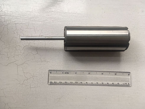
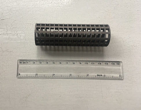
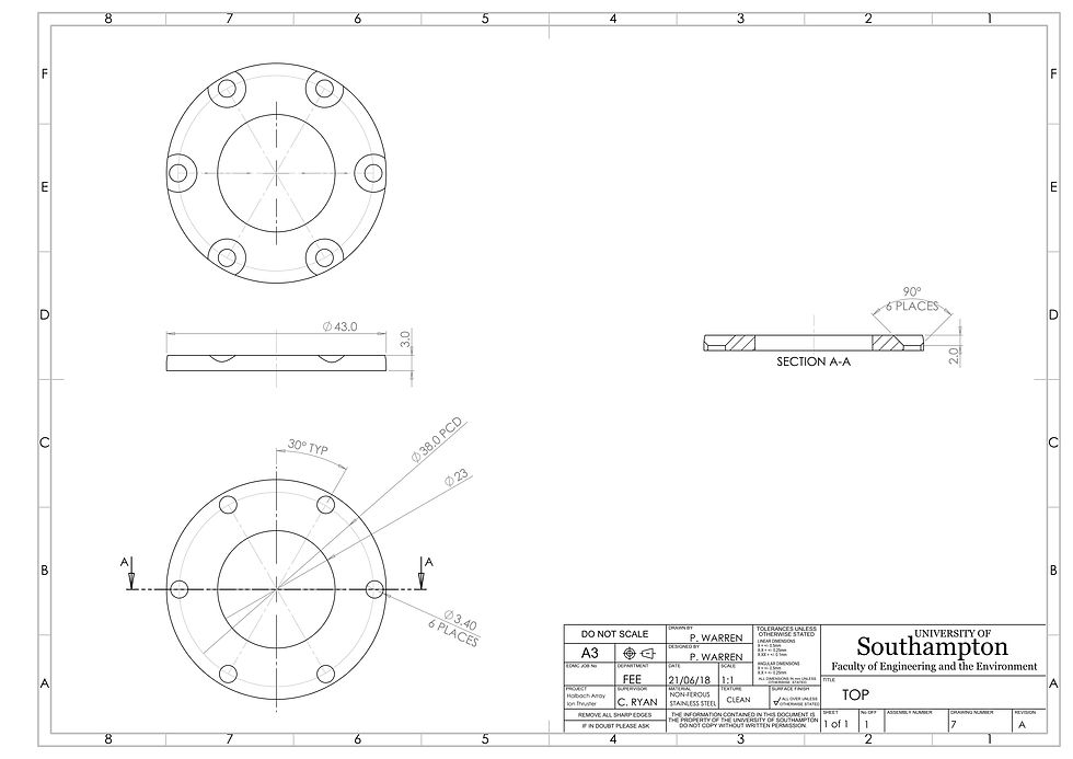
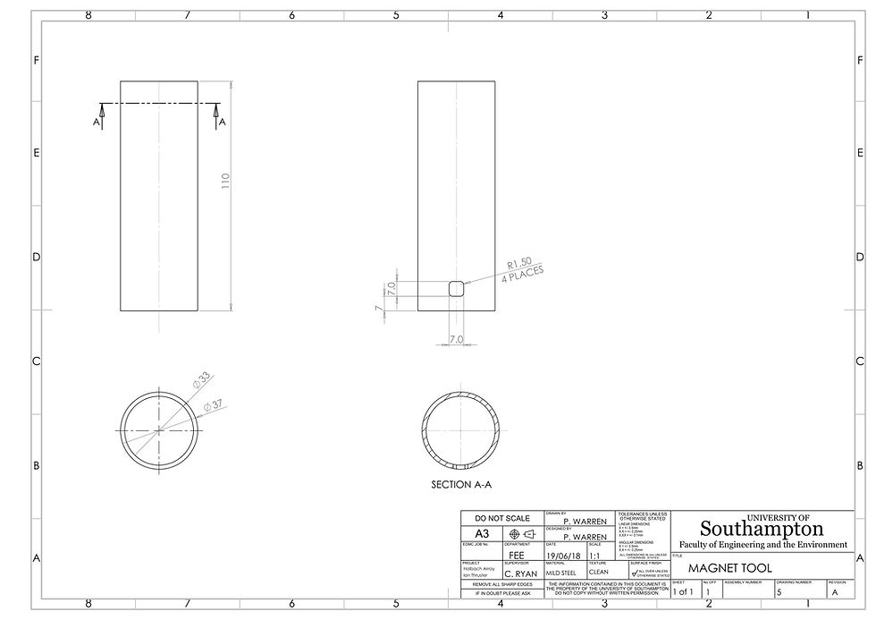
CAD Drawing and Working With Machinists
I worked closely with the university manufacturers. Due to the tough material requirements the manufacture presented some challenges. 3D printed aluminium required significant time to remove support material.
The anode was made in two sections and soldered using silver solder as typical solder would melt.

Written Report
My Dissertation was written in LaTeX and can be downloaded in full here. It contains a view of more conventional thruster designs, a thorough mathematical analysis of magnetic mirroring and a review of the project.
